
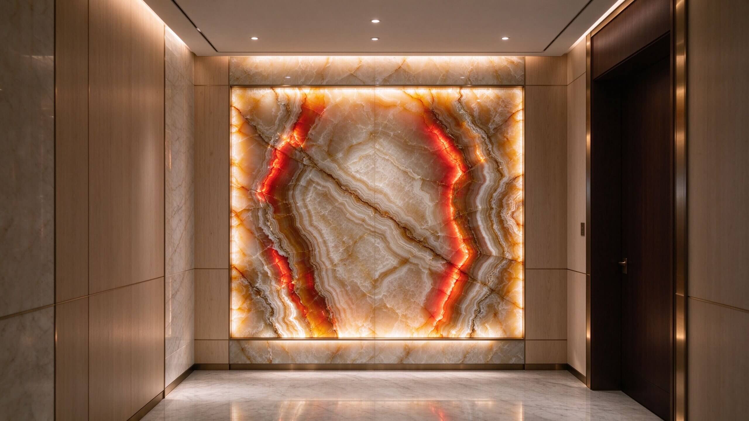
MỘT custom LED sheet backlighting system is how you light a surface, not a line. Instead of a strip inside a channel, you place a flat, cuttable sheet of LEDs behind onyx, marble, acrylic, fabric or a graphic diffuser, and the front material glows evenly from edge to edge.
This guide walks through the whole build in the order that actually matters on site: define the effect, measure the cavity, choose the sheet format, count the sheets, size the driver, wire and mount, then test before anything is closed up. It also covers the two things that decide whether the result looks expensive or amateur — light mixing distance Và power distribution — plus a fault table for the uneven panels you have probably already seen.
Mục lục
- What Is an LED Sheet Backlighting System?
- Step 1 — Define the Application and the Effect
- Step 2 — Measure the Area and the Cavity Depth
- Step 3 — Choose Modular, Long-Roll or Cut-to-Shape
- Step 4 — Calculate How Many Sheets You Need
- Step 5 — Size the Driver and Split the Load
- Step 6 — Wire, Mount and Respect Series Limits
- Step 7 — Dry-Fit Before You Close the Panel
- Common Mistakes Behind Hotspots and Dark Patches
- Where LED Sheet Backlighting Works Best
- KayTai Sheet Panels and Matching Profiles
What Is an LED Sheet Backlighting System?
An LED sheet is a flexible printed circuit board carrying a dense array of chips — typically 100 to several thousand per sheet — with a cuttable grid and connectors along the edge. Because the chips are spread over the whole area rather than packed into one line, the sheet produces a broad light field that a diffuser can blend into a uniform surface.
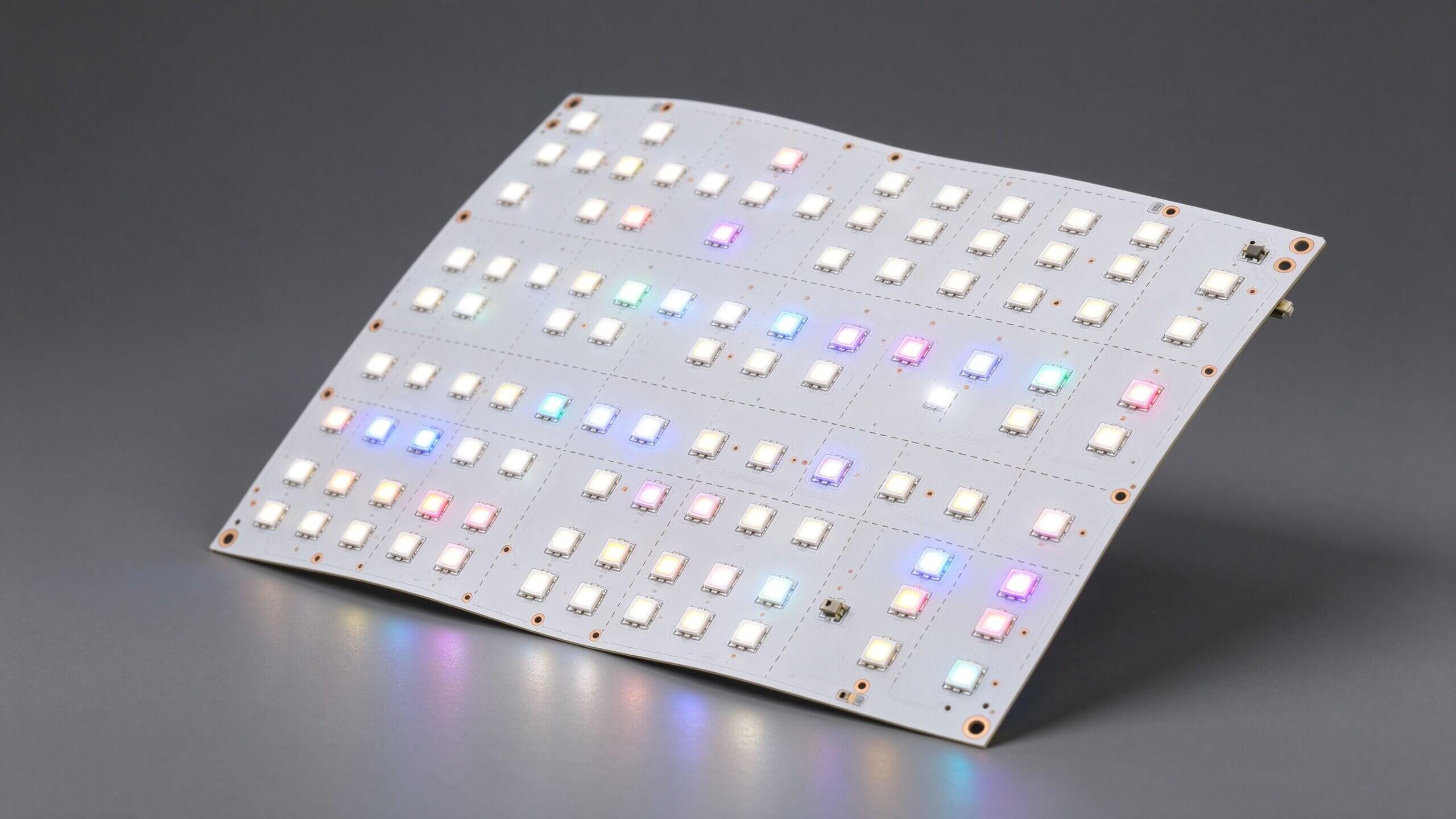
Three properties make it the right tool for backlighting: it is thin (often 1–3 mm, so it fits shallow cavities), it is cuttable on marked lines so it can follow corners and cut-outs, and it is modular — sheets daisy-chain so one driver can feed a large surface.
Area, not line
Designed to cover a surface. A strip lights an edge; a sheet lights the whole face behind a translucent material.
Cut on the grid
Most sheets are cuttable in 1-light, 3-light or 6-light modules, so irregular stone, L-shapes and corners can be covered without oversized gaps.
Thin enough to hide
A 1–3 mm sheet plus a 2–5 mm diffuser fits cavities that a strip-and-channel build could never squeeze into.
If your project is linear rather than areal — cove lighting, under-cabinet runs, skirting or a ceiling trench — a strip in a profile is cheaper and easier. Start with our Hướng dẫn sử dụng đèn LED dải hoàn chỉnh, or go straight to under-cabinet LED lighting if that is the job.
Step 1 — Define the Application and the Effect
Before sheet size or wattage, answer one question: what must the surface look like when it is switched on? The answer decides density, diffuser grade and colour temperature far more than the budget does.
Functional light
Menu boards, lightboxes and work surfaces. Priority: lumen output and measurable uniformity, not mood.
Decorative glow
Feature walls, headboards, bar fronts. Priority: soft, continuous light with no visible chips and no bright frame lines.
Both
Retail displays and hotel lobbies, where the surface must glow and also read as lit. Balance brightness against diffusion.
Use this table as a starting point, then confirm with a physical sample — the front material changes everything.
| Ứng dụng | Typical cavity depth | Format that usually works |
|---|---|---|
| Backlit onyx / marble feature wall | 30 – 80 mm | Modular sheets in a grid, or cut-to-shape around veining |
| Kitchen island / bar counter | 40 – 90 mm | Modular 480 × 240 mm grid or long-roll runs |
| Lightbox / menu board / signage | 60 – 120 mm | Long-roll, high density, single continuous run per band |
| Display cabinet, shelf, niche | 20 – 40 mm | Small modular sheets or narrow cut sections |
| Headboard / fabric panel | 20 – 50 mm | Modular sheet, warm CCT, low-glare diffuser |
One warning that saves rework: a shallow cavity does not just need a brighter sheet. It needs a tighter pitch, a stronger diffuser, or both — covered in Step 2.
Step 2 — Measure the Area and the Cavity Depth
Three numbers decide whether the finished panel looks even: total area, cavity depth, and the LED pitch of the sheet you are considering. Measure all three before you order, and measure the usable depth — structure, brackets and cable entries all eat into it.
| What to measure | Why it matters |
|---|---|
| Overall width and height of the lit area | Sets total coverage and the sheet count; do not measure the frame, measure the visible face |
| Usable depth from sheet surface to diffuser | This is the mixing distance — the single biggest factor in hotspot control |
| Diffuser type and thickness (PMMA / PC, 2 / 3 / 5 mm) | Sets transmission and haze; a 2 mm clear panel hides nothing |
| Front material translucency | Onyx glows; painted MDF does not. Verify with a sample before ordering wattage |
| Power location and cable route | Decides zone splitting and whether you can reach the driver for service |
| Access panels and fixings | A sealed cavity with no access is a maintenance trap |
The most useful rule in backlighting is about geometry, not materials: the distance from the LEDs to the diffuser should be at least equal to the LED pitch, and ideally 1.5–2.5 times the pitch. Below that, individual chips punch through no matter how good the diffuser is.
| LED pitch on the sheet | Minimum mixing distance | Comfortable distance |
|---|---|---|
| 10 mm | 10 mm | 15 – 25 mm |
| 20 mm | 20 mm | 30 – 50 mm |
| 30 mm | 30 mm | 45 – 75 mm |
Around 20 mm spacing is a practical reference for shallow backlit cabinets, but treat it as a starting point rather than a rule — beam angle, diffuser haze and the front material all shift the result. In the display industry the same relationship is tracked as an A/P ratio (distance to active area versus LED pitch), with A/P ≥ 0.8 treated as controllable. For thin translucent stone only a few millimetres thick, keep at least 50 mm of spacing to the surface or you will see the chips through the veining.
Also plan the perimeter. Gaps at the edge of a sheet read as a dark frame line, so either run the sheet close to the edge with a reflective liner, or accept a deliberate border and design it in.
Step 3 — Choose Modular, Long-Roll or Cut-to-Shape
Sheets come in three practical formats. The choice is mostly about geometry: how regular the surface is, and how many connections you are willing to make.
| Format | Typical size | Cắt | Connections | Tốt nhất cho |
|---|---|---|---|---|
| Modular sheets | 250 × 250 mm up to 480 × 240 mm | On the grid, in 1 / 3 / 6-light modules | Daisy-chain quick connectors | Grid layouts, cabinets, small or broken-up areas |
| Long-roll sheets | 240 mm wide, up to 10 m per roll | At marked intervals only | Screw terminals, no soldering | Large flat uninterrupted surfaces, lightboxes |
| Cut-to-shape | Custom outline per drawing | Follows the contour, soldered joints | Soldered or custom harness | Irregular stone, curved returns, corner cut-outs |
Option A — modular grid (4 × 4 = 16 sheets)
Even coverage, many small connection points.
Option B — long-roll bands (4 runs × 2 m)
Fewer joints, better voltage stability, cleaner surface.
Rule of thumb: if the surface is regular and wider than about 1 m in both directions, long-roll wins on joints and voltage stability. If there are corners, cut-outs or structural returns, modular or cut-to-shape keeps the light close to the edge. For a shallow niche, small modular sheets beat a big one simply because you can fit them.
Step 4 — Calculate How Many Sheets You Need
Worked example used throughout this guide: a backlit kitchen island panel, 1830 × 915 mm (72 × 36 in), 50 mm cavity, onyx front.
Option A — 480 × 240 mm sheets
1830 ÷ 480 = 3.8 → 4 sheets across
915 ÷ 240 = 3.8 → 4 rows
4 × 4 = 16 sheets
16 × 45 W = 720 W total load
Option B — 240 mm × 2 m rolls
915 ÷ 240 = 3.8 → 4 bands
Each band covers 1.83 m
4 × 2 m = 8 m of sheet
4 × 96 W = 384 W total load
Always round up, then add margin for edge trim and mistakes: 10–15% extra sheet area is normal on a first build, less on repeat production. If you cut, count the cut lines rather than the area — a sheet cut into 3-light modules cannot then be cut into 1-light modules, so plan the module size once.
Note the power difference between the two options for the same surface: 720 W versus 384 W. Option A uses denser, brighter sheets; Option B uses fewer, longer runs at lower wattage. Neither is “better” — one is brighter and easier to service, the other has fewer joints and less load on the driver.
Step 5 — Size the Driver and Split the Load into Zones
Power is where most flickering and dim-end problems start. Do the arithmetic before you buy: total load, safety margin, driver count, then zones.
| Item | Option A (16 sheets) | Option B (4 × 2 m rolls) |
|---|---|---|
| Connected load | 720 W | 384 W |
| Recommended margin (20–30%) | 864 – 936 W | 460 – 500 W |
| Typical driver choice | 1 × 1000 W 24 V, or 2 × 500 W | 1 × 500 W 24 V |
| Controllers needed | 2 for dimming at this load | 1 |
Zone the load
Treat every 300–400 W as a zone with its own driver output and return. If one zone dims, you can find it without opening the whole panel.
Keep runs short
Long DC cable adds resistance. Feed each zone from its own output rather than daisy-chaining 20 m of 24 V cable.
Match the control
Tunable white needs a two-channel driver. Addressable sheets need their own protocol — never mix them with standard dimming sheets on one controller.
Headroom is not optional. An undersized driver shows up first as flicker at low dim levels, then as a shortened life. If your total lands near a driver rating, step up a size rather than running at 95%.
For long 24 V runs, check the actual drop before installation with our LED voltage drop calculator. A 1 V drop at the end of a run is visible as a dim band on a backlit surface, even when the driver is correctly sized.
Step 6 — Wire, Mount and Respect Series Limits
Both formats follow the same mounting logic: a clean, flat surface, high-adhesion backing for alignment, and mechanical fixings wherever the panel will be serviced or where heat builds up.
| Limit | Modular sheets | Long-roll sheets |
|---|---|---|
| Maximum per series run | About 5 sheets | Up to 10 m continuous |
| Connector current capacity | 5 – 6 A | About 10 A |
| What happens past the limit | Voltage drop, dim end of run, heat at the connector | Fade along the last metres, warm connector |
Wiring discipline that prevents most callbacks: keep polarity consistent between sheet and driver, keep AC and DC separated, gland the entry point, and fuse the DC side. In wet or outdoor locations the sheet itself is not the waterproof element — seal the cavity, use an IP-rated diffuser assembly, and keep the driver in a dry enclosure.
If the same project also has straight runs along the panel edge, our drywall LED channel guide và flexible aluminum channel guide cover the linear side of the build.
Step 7 — Dry-Fit Before You Close the Panel
This is the step almost everyone skips, and the one that catches the expensive problems. Test the optical stack before the panel is sealed.
Mount temporarily
Lay the sheets in position without final fixings. Route the cables as they will actually run.
Power every zone
Switch on zone by zone. A zone that is visibly dimmer than its neighbour is a wiring or load problem, not an optics problem.
Put the real front material on
Place the actual onyx, acrylic or diffuser. Never judge uniformity from bare LEDs.
Inspect at viewing distance
Stand where the client will stand. Check centre, edges, seams and the areas around power feeds, then photograph at a fixed exposure.
Set a target before you look: a brightest-to-darkest ratio of about 8:1 or tighter reads as smooth on a backlit surface. If you can see chips at normal viewing distance, do not add more LEDs first — fix distance, diffuser or sheet spacing, in that order.
Record the pass: photograph with the same exposure and settings, and keep the approved sample. It becomes the reference for the rest of the production run, and it settles arguments later far faster than opinions.
Common Mistakes Behind Hotspots and Dark Patches
Almost every uneven backlit panel traces back to one of these. Diagnose by the shape of the fault before changing components.
| Triệu chứng | Most likely cause | Sửa chữa |
|---|---|---|
| Visible rows of dots | Mixing distance shorter than the LED pitch | Increase cavity depth, tighten pitch, or move to a higher-haze diffuser |
| Dark band at a seam | Sheets spaced too far apart, light fields do not overlap | Close the gap or add a bridging cut section |
| One end of a run is dimmer | Voltage drop, series run over the limit | Shorten the run, inject power at both ends, split the zone |
| Warm or pink tint toward one end | Voltage drop plus bin/colour shift between sheets | Keep one bin per panel, split zones, feed from both ends |
| Bright frame line around the edge | Structural shadow or reflective liner ending short | Extend the liner, run the sheet closer to the edge, mask the transition |
| Flicker at low dim levels | Driver near its rating, or controller mismatch | Step up the driver size, confirm protocol compatibility |
| Panel dims over months | Heat build-up in a sealed cavity | Ventilate the cavity, derate the load, use thermal tape and fixings |
Two more habits prevent trouble: cut only at the marked cut lines (a wrong cut severs a circuit and cannot be repaired), and store sheets dry — humidity oxidises soldered joints and shows up later as an intermittent dim section.
Where LED Sheet Backlighting Works Best
The format wins wherever a surface needs to glow rather than be lit from outside. These are the applications that come up most often in project enquiries.
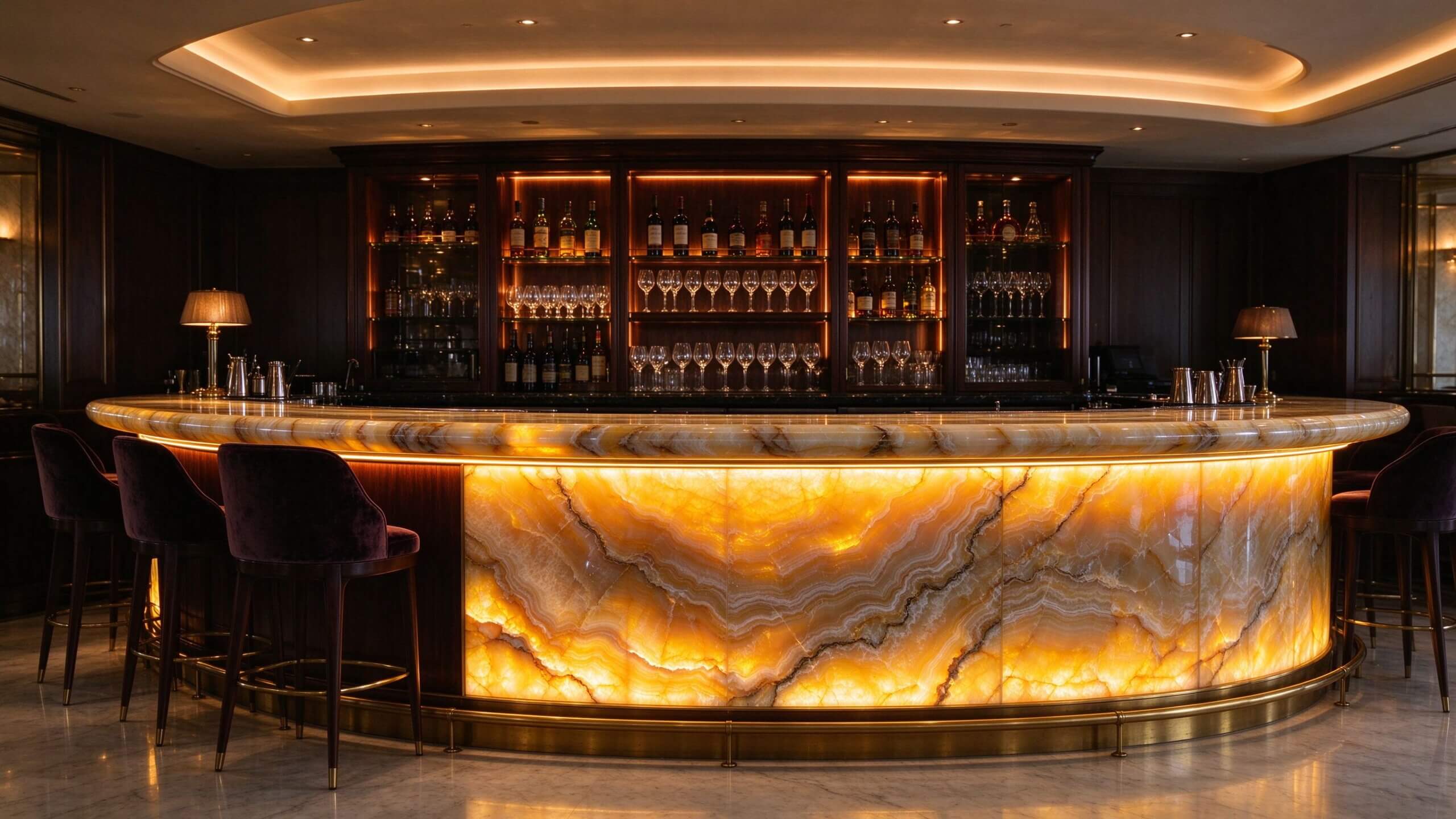
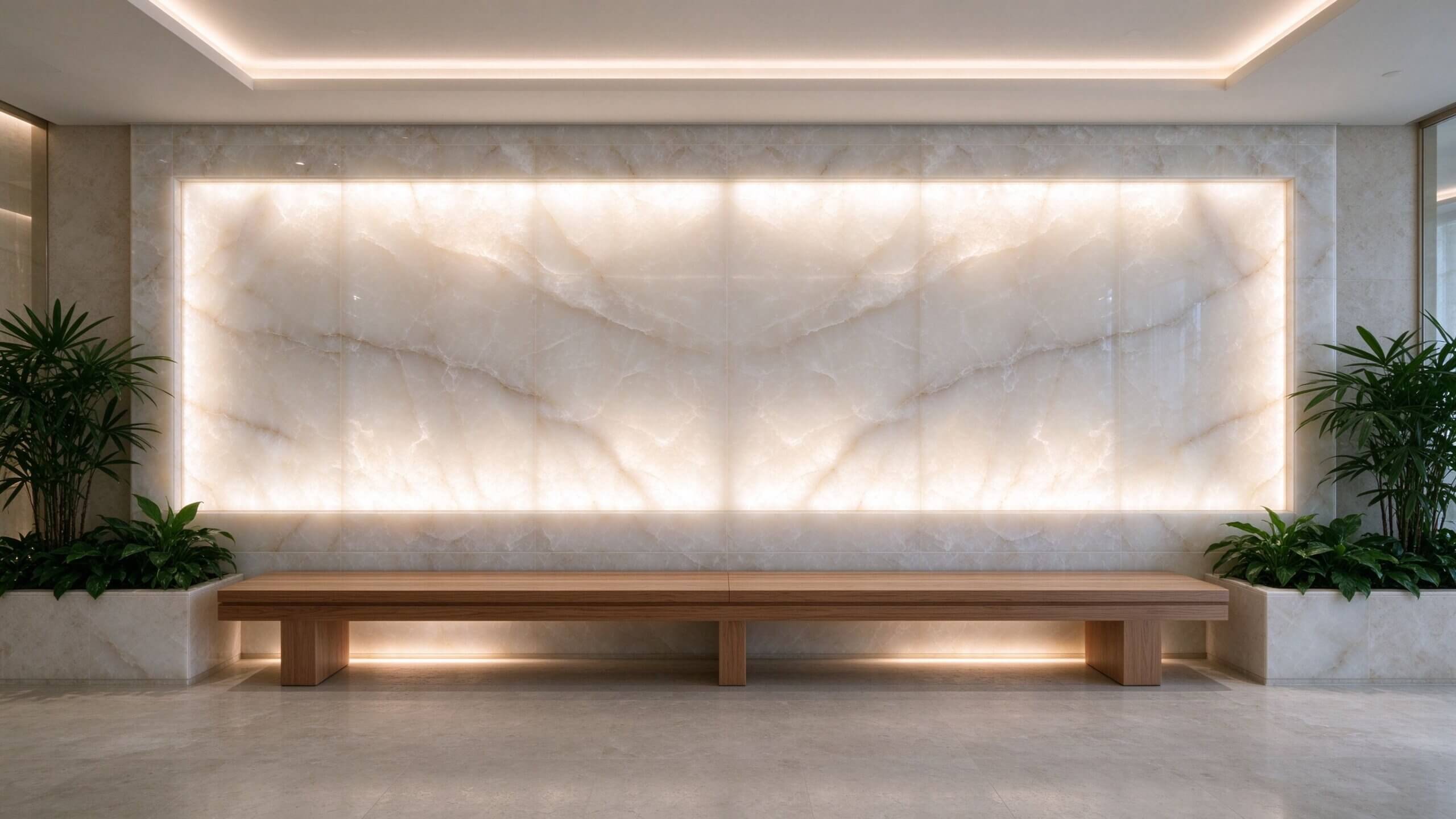


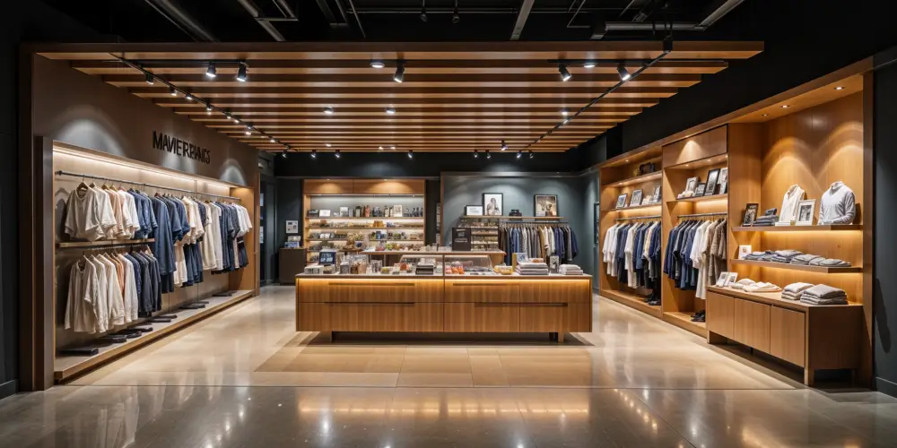
One caution for stone projects: veining and thickness variation change the transmission, so a visually darker patch may be the material, not the lighting. Test with the actual slab before you change the electrical design.
KayTai Sheet Panels and Matching Profiles
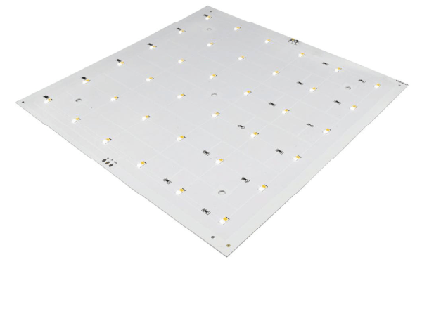
KayTai supplies cuttable LED sheet panels and the profiles for the linear edges of the same project. Both are available with custom size, CCT, CRI and voltage on project orders.
Related ranges
For the linear edges of the same panel, or for tunable-white accents around it:
Dải đèn LED trắng có thể điều chỉnh — two-channel CCT control
Hồ sơ nhôm LED — recessed, surface and corner channels
LED Sheet Backlighting FAQ
▶How many LED sheets do I need for my backlit panel?
Divide the lit width by the sheet width and the lit height by the sheet height, round both up, then multiply. A 1830 × 915 mm panel with 480 × 240 mm sheets needs 4 × 4 = 16 sheets. Add 10–15% for edge trim on a first build.
▶How far should the LED sheet be from the diffuser?
At least the LED pitch, and preferably 1.5–2.5 times the pitch. With 20 mm spacing, plan 30–50 mm of usable cavity depth; for thin translucent stone keep at least 50 mm to avoid visible chips.
▶Can I cut an LED sheet panel?
Yes, but only on the marked cut lines, usually in 1-light, 3-light or 6-light modules. A cut through a circuit cannot be repaired, so plan the module size before you start.
▶Is an LED sheet better than an LED strip for backlighting?
For an area, yes: the sheet covers the surface and hides behind a diffuser. For a linear run — cove, under-cabinet, skirting — a strip in a profile is cheaper, easier to service and better at throwing light along a line.
▶What power supply does an LED sheet system need?
A 24 V constant-voltage driver sized at 1.2–1.3 times the connected load, split into zones of roughly 300–400 W. Use a two-channel driver if the sheets are tunable white.
▶Why does my backlit panel look uneven?
In order of likelihood: mixing distance shorter than the LED pitch, sheets spaced too far apart at seams, voltage drop at the end of a long run, a diffuser with too little haze, or the front material itself varying in thickness and transmission.
▶Can LED sheets be dimmed or colour-tuned?
Yes, with a matching driver and controller. Tunable white sheets need a two-channel driver and a controller that supports CCT; addressable sheets need their own protocol and cannot share a controller with standard dimming sheets.
▶Are LED sheets suitable for bathrooms or outdoor use?
The sheet is low-voltage but not waterproof by itself. Seal the cavity, use an IP-rated diffuser assembly and keep the driver in a dry enclosure. For exposed outdoor surfaces, an IP65+ strip or a sealed panel assembly is the safer route.
Have a Backlit Panel to Specify?
Send us the lit dimensions, cavity depth and front material. Our engineers will come back with a sheet layout, driver sizing and a sample for dry-fit testing.
Liên hệ KayTai